|
G3VjV
Station and Magnetic Loop Antennas
(To
be continued)
 |
|
The Big Loop
|
|
| |
|
 |
 |
The simple matching loop, see radial
section for balun.
This loop covers 1.3 MHz to 6.5 MHz.
|
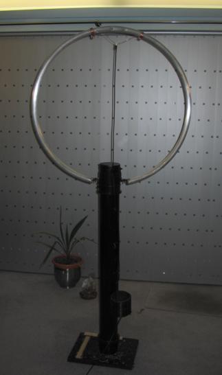
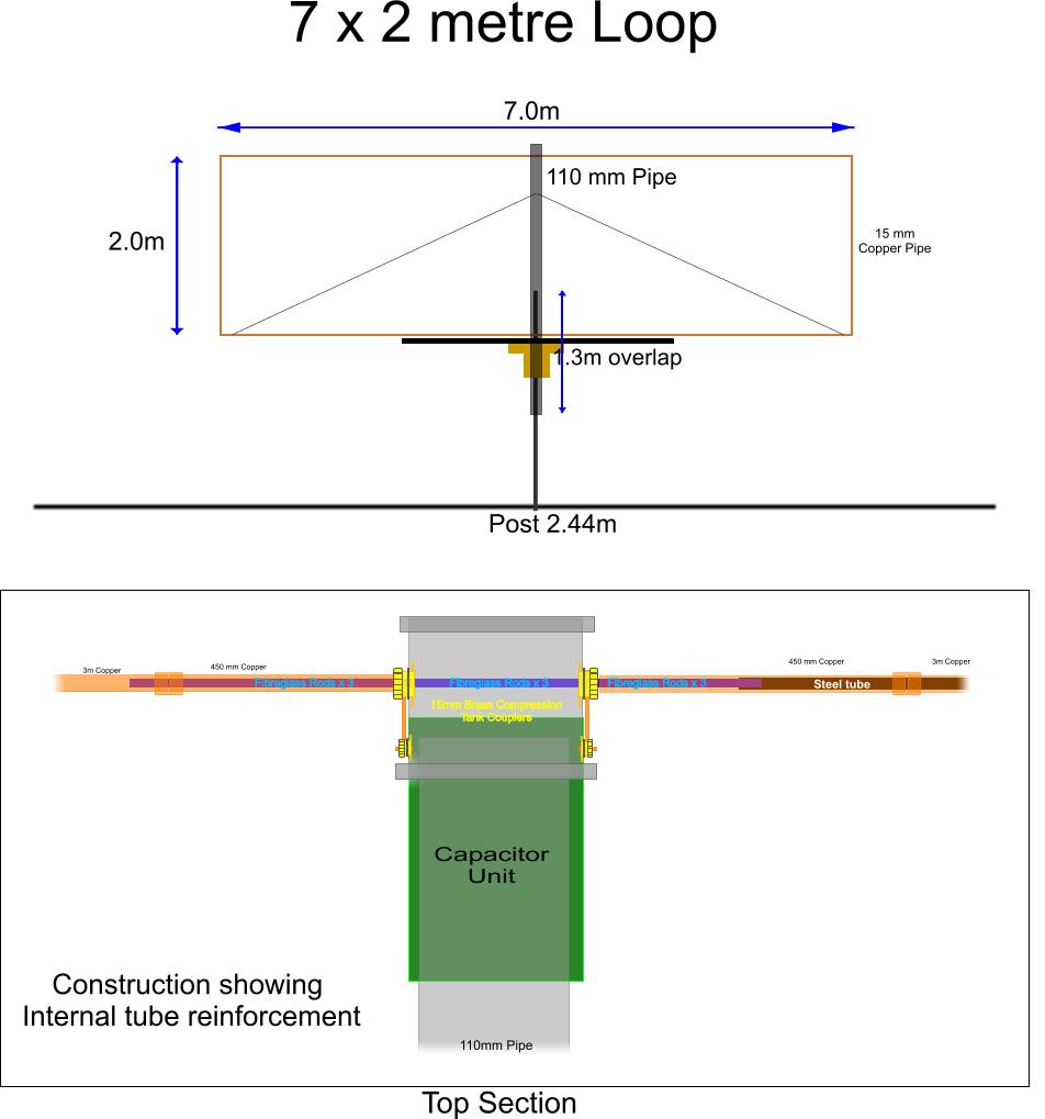
Details of the 7 by 2 metre loop
The 7 x 2 metre loop.
The loop is made from 22mm copper tube the corners are
bent with a pipe bender, the joins are made with electronics grade
solder and the lower half is strengthened with steel tube, I have
used 110 mm plastic waste pipe for support, this slides over a wooden
fence post and can easily lowered and raised for servicing, the
antenna if fed as a balanced system, rather than
a simple gamma match, the intention is to reduce noise pick-up and
ensure the minimum amount of R.F. on the centre line of the loop,
the balun is made from 30 metres of coiled co-ax. |
This loop is constructed from 22
mm tube, the top section is reinforced with fibre glass rod, all other
joins are reinforced with 1 metre lengths of 10mm steel tube.
This Loop covers 1.3 to 6.5 MHz so can't be used
on 40m but reports suggest it is working very well on 160, 80 and 60m
so I think it is worth the loss of 40m
Matching is by balanced tappings via an air spaced
Balun..
The bandwidth on 160m is just over 3 KHz so is
easier to tune and allows full bandwidth audio.
 |
|
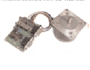
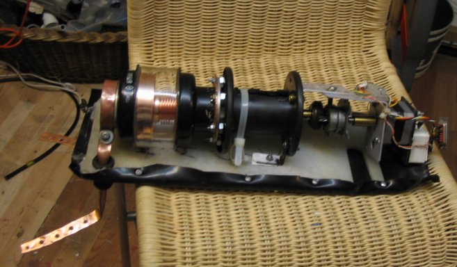
The Capacitor:
The capacitor is a 1200 to 10 pf vacuum type, this is driven
by a stepper motor via a 5:1 gearbox, the stepper motor is controlled
by a pc via a USB port.
|
The old serial stepper motor and driver boards were supplied
by Maplin, order #: RM75S, Maplin no longer supply this item but
it is still advertised on the Milford Web site, see further down
for the USB Stepper Motor Controller
Bipolar Stepper Driver Set (#5-595)
Milford House
120 High Street
South Milford
LEEDS LS25 5AQ
ENGLAND
Tel: 01977 683665; Fax: 01977 681465
|
|
|
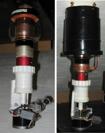
The 80 cm (Flash Gordon) Loop
This loop covers 10 MHz to 29.7 MHz, the loop itself is from a
prototype Catco Antenna but with a new housing, motor and gearbox,
(the gear box had not been fitted when the photos below were taken).
The capacitor is at the bottom in this version and is housed in
the mounting tube, the tube is 110 mm plastic waste pipe, this antenna
is fed with a bal un and has a good SWR on all bands.
The capacitor is 10pf - 500 pf and is really too high a capacitance
for 10m, I had to redesign the way it connects to the loop in order
to get the thing to resonate above 28.45, on the lower photo you
can see the connections are now on the side of the housing.
A single length of co-ax feeds the top, the double image is a shadow.
|
The completed loop awaiting to go outside.
|
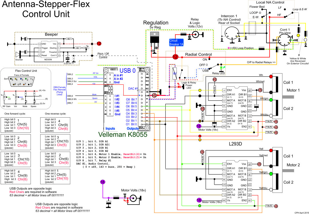
USB Stepper Motor Controller
The USB Stepper Motor Controller, it consists of a Velleman K8055
USB Experiment Interface Board, this is the same board I use in
my Home Control system, if has 8 Digital Outputs, 2 Analog Outputs,
2 Analog Inputs, 5 Digital Inputs per board.
I use 4 of the digital outputs to control the 4 inputs of two L293D
Driver chips, another two bits control the Enable pins
of each chip, a total of six output lines control the two stepper
motors.
This system is faster and more reliable than the previous RS232
controllers, the only downside is the code is more complicated,
as I have implemented Ramp Up and Ramp Down to ease the strain on
the motor and gearbox.
The Analog and digital inputs are used for controling Volume, RF
Gain, Mute & Squelch to the Flexradio over TC/IP.
|
 |
| |
The Controller
|
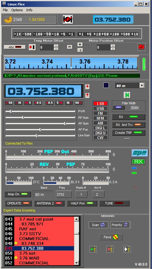
Software Control
| |
|
| 
|
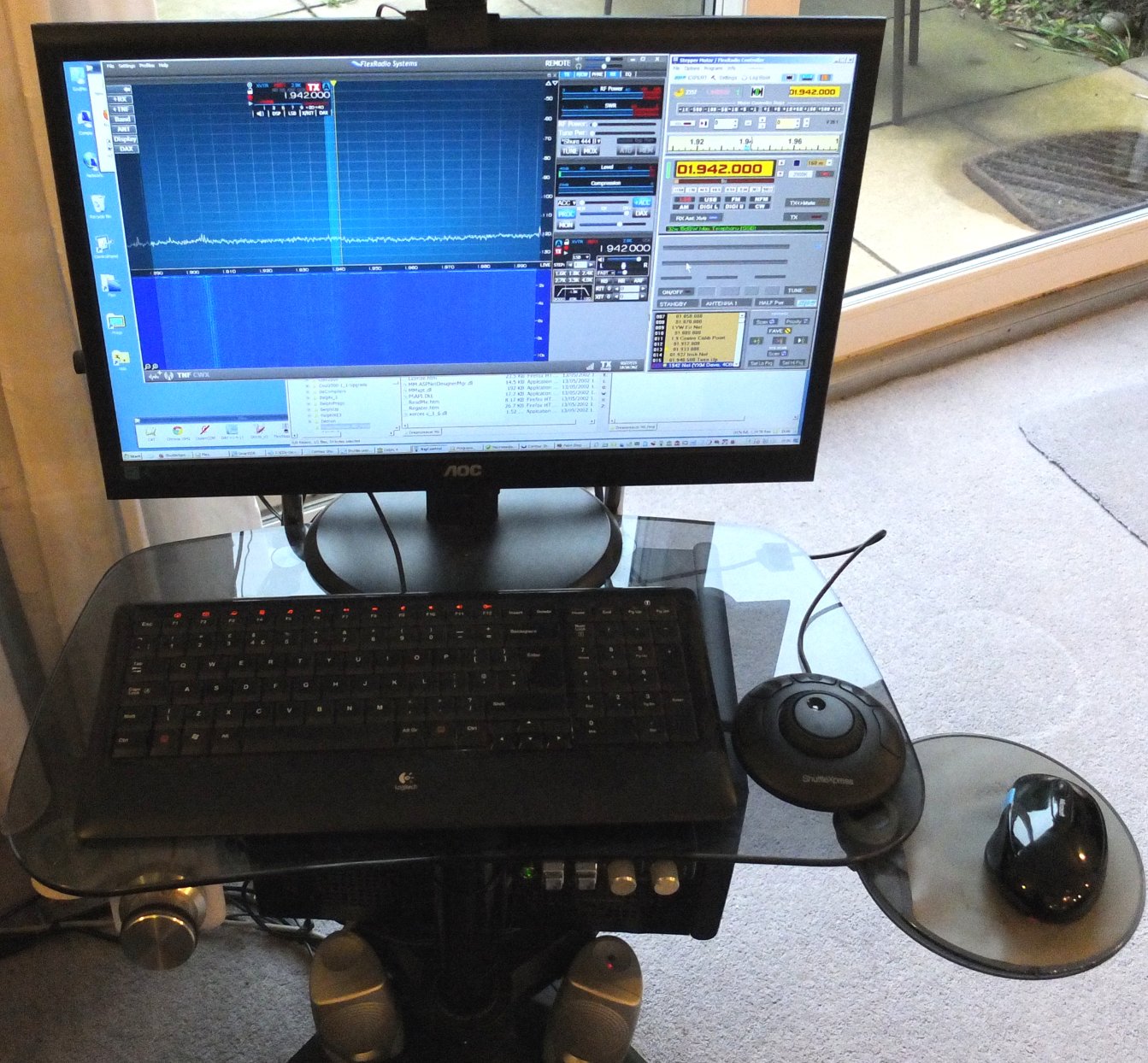
The software for interacting with the rig, linear and controlling
the stepper motor(s), uses TC/IP for FlexRadio.
The image above shows the Motor control section at the
top, Radio controls, Linear and Memories at the bottom.
The program continuously monitors the frequency the rig
is tuned to and sets the stepper motor to the correct position,
fine tuning of the antenna can be done with the Griffin Controller
(on transmit) or the left and right scroll keys.
I have also implemented an unlimited number of memories,
each one can be titled.
The usual scan, priority and memory scan are also implemented
in addition any memory can be set as a "Favourite".
I use Delphi to write the software.
|
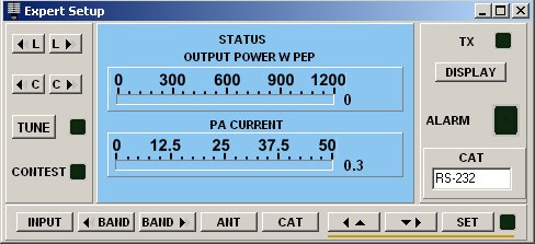
Linear Control Page |
Linear Control Page:
Just emulates the Linear control and displays.
|
Griffin PowerMate USB controller
I installed a Griffin PowerMate USB controller
(see picture further down) I can really recommend this product,
it is a very well made and versatile unit,.
Latest:
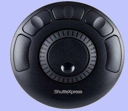
The Contour Shuttle USB controller
I now am also using the Contour Shuttle
controller, it as central jog wheel which I use as a VFO controller,
a Shuttle controller which I use to spin the VFO fast in either
direction and 5 buttons, at the moment I am using two of them, to
change bands.
It is easy to set up and very nice to use.
|
 |
Noise -- EMC -- QRN
Like most people using radio I have recently experienced
increasing problems of noise from Switch Mode Power Supplies etc.
I managed to trace and fix most of the sources from within my own
property, the worst offender being my Draytek Router, this transmitted
noise from its power supply all round the house via the Cat5 cabling
but it is very difficult to deal with noise from adjacent properties,
you cure one and then another problem pops from another source!
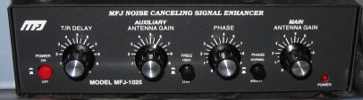
I decided to try the noise canceling approach, I purchased
the MFJ-1025 Noise Canceling Signal Enhancer, this device combines
the signals from the Main Antenna and a Noise Pick-up Antenna and
by adjusting the phaze and Amplitude it is possible to null out
most of the noise, setting up the Noise Pick-up Antenna correctly
is crucial, it must pick-up the same noise sources as the main antenna
but not too much of the signals you want to hear! |
|
Using the MFJ-1025 in conjunction with a transmitter requires
care, the Noise Pick-up Antenna can pick up large amounts of RF
from the transmitter and damaged the unit, I have attempted to prevent
damage by shorting out the Noise Pick-up Antenna when transmitting,
below is a circuit I use, I have included a buffer from the Transceiver
T/R line , the MFJ has a relay and my Antenna muter also has another
relay.
I have a RF amplifier to bring the noise levels up to a
suitable level and a choice of several Noise Antennas, a 30 cm length
of wire stuck to the party wall to pick up my neigbours numerous
switched mode PSUs, I have a Wellbrook Loop Antenna and three wire
antennas running in different directions some distance from the
house.
|
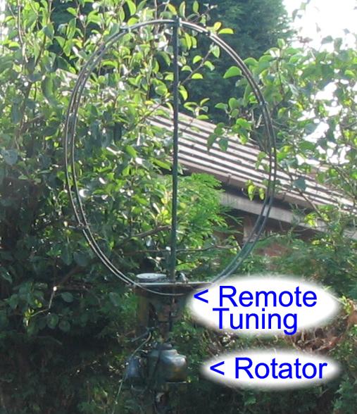
The receiving Loop.
(This is now a Wellbrook Loop so no need for remote tuning)
|
|
|
The
Counter-Poise/Radial System |
|
Because my loop is too close to the ground there is a
large amounted of radiation absorbed by the ground so I have now
added a system of radials to my system, this has definitely improved
reports on 160 and 80 metres.
I have four radials that are resonated, one for 80 m that
is self resonant, one for 160 that has a small inductor to bring
it to resonance, one that has a relay switching in inductors for
160 or 80 and another resonated on 160m.
I have one long un resonated radial that runs directly
under the antenna and to each side, a total length of over 45 metres.
All the conductors close to the antenna are of old copper
pipe, a mixture of 28mm, 22mm and long sections of 10mm, in the
picture below there are sections running under the grout between
the flags.
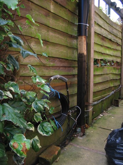
The new balun (30m length) and part of
the radial system.
|
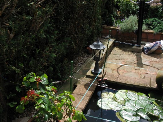
The last section of a 80m radial runs
round the pond.
|
My
Station
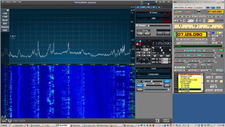 . .
PC Screen Showing SDR software and my redesigned Rig /
Loop Controller
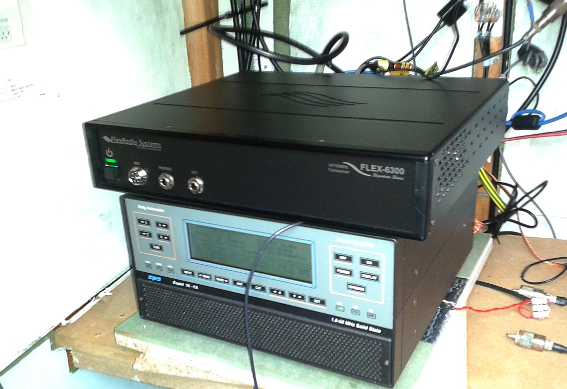
Remote gear, SDR control via WiFi
Flex
Demo (mp4, 38mb)
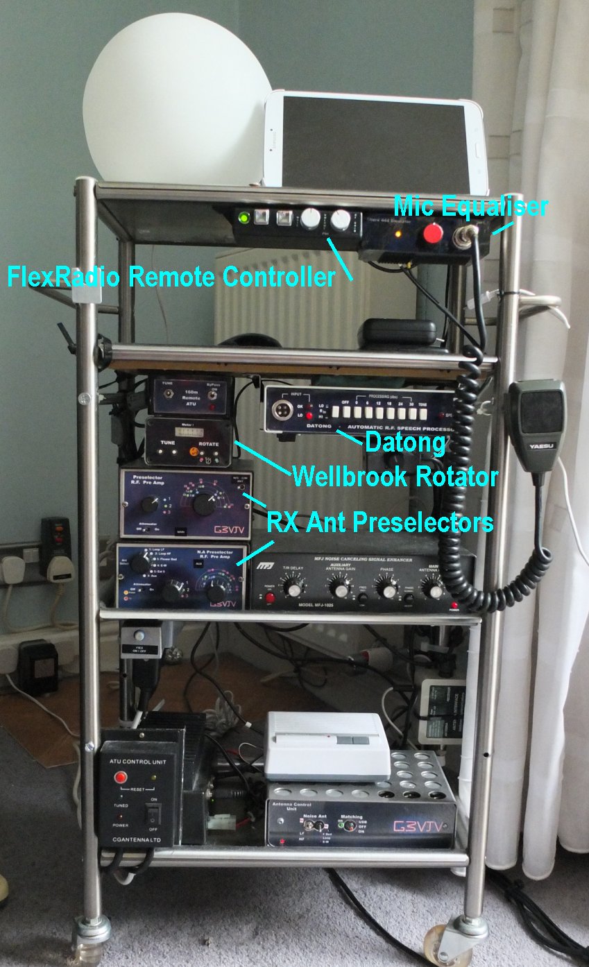 
Remote controller Station
Misc. Rally Slides

|